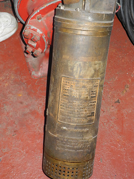
| The electric submersible pump (sub pump), with the
old style bronze body, was in service from the 1940s
through 1970s. It was extremely useful, although heavy
at 156 pounds, in dewatering. All U.S. Navy surface
ships were required to have them; one to six were
provided in repair lockers on the hull and DC allowance,
depending on the size of the zone or area of
responsibility and the ship’s class. The submersible
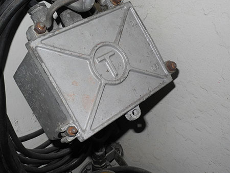
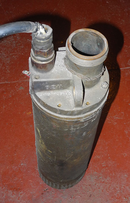
pump was a water-cooled pump powered by 440 volts. It
was equipped with a 2 ½-inch male suction connection, a
2 ½-inch male discharge connection with handle, a
50-foot line for lowering the pump, and a 50-foot
electrical cable with switch. The electrical cable was
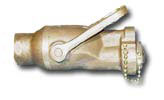
joined to the lowering line. A foot valve acted as a
check valve and allowed the pump to be primed. The
suction hose was a 2 ½-inch, 10-foot long hard rubber
hose. The rate or gpm of the sub pump varied according
to the static head (i.e., the vertical distance the
water had to be pumped). The larger the static head, the
less it would pump. The rate of the sub pump was 180 gpm
at 50 feet of static head or 140 gpm at 70 feet of
static head. The sub pump was designed to pump a variety
of liquids. The sub pump could pump water, diesel fuel,
JP-5 and light oil. It was not designed to pump some
fluids, such as gasoline, heavy oil and hot water
because of explosion hazards or because the fluid would
not cool the pump properly. The star strainer was a
cylindrical, perforated, corrugated metal strainer. The
corrugated folds looked like a star from the top, giving
the strainer its name. The sub pump fit snugly inside
the star strainer, and the strainer was then screwed
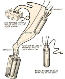
onto the suction side of the pump. To overcome large
discharge static heads on larger ships, two or more sub
pumps were connected together in series or in tandem.
Because the higher of the two pumps was not submerged,
the lowest pump had to always be energized first. Once
water filled the second pump, it could be energized
also. To the left is a diagram of two sub pumps running
in tandem. A 2 ½-inch double female adapter was needed
to connect the discharge from pump #1 to the suction of
pump #2. The submerged pump was inserted in a basket
strainer. A special connector allowed three pumps to be
connected to a single 440-volt outlet. Below is a table
of manufacturers’ submersible pump limitations. |