Installed carbon dioxide (CO2) systems were
provided on ships for paint lockers, flammable liquids stowage
lockers, emergency diesel generator rooms, aviation gas pump
rooms, piping and piping cofferdams.The American La France
Foamite (ALFITE) Corporation system could consist of one or more
cylinders. When more than one cylinder was used, they were
arranged to be operated as a single unit.
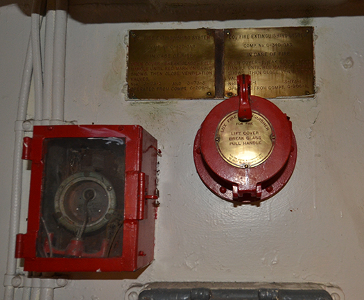
Two different types of ALFITE systems were available. Both
systems operated from break-glass pull boxes. The cable from the
pull boxes was attached to the lever head on the first cylinder
valve. When more than one pull box was used, a dual control tube
was provided at the location where the pull cables came together
and were joined.
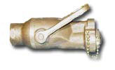
- The type “D” system had a single passageway through the
cylinder valve through which the cylinder was charged,
discharged or through which the cylinder pressure was
relieved should the pressure have become excessive. The
valve body forging contained the cutter valve assembly. In
systems made up of more than two cylinders, the first two
cylinders were equipped with lever heads and were known as
the pilot cylinders. The remaining cylinders were equipped
with pressure heads and were known as the battery cylinders.
- The type “M” system had a three-port valve with a
separate port for charging, safety and discharge. A cutter
head assembly was attached to the cylinder by means of a
swivel nut. The cutter head assembly contained a piston as
an integral part. When it was used on the first two
cylinders of a system, the protective cap was removed from
over the cutter knob and a lever head was attached. Inasmuch
as the cutter head assembly was essentially a pressure head,
no other part other than the cutter head assembly was
required on the remaining cylinders.
In either system, the first two cylinders were operated
mechanically either from pull boxes located a distance from the
cylinders or by lever heads located at the cylinders.
When the lever heads were operated, the valve cutter was
depressed and the gas sealing disc was cut, discharging gas into
a manifold and to the pressure heads on the remaining cylinders.
On the type “D” system, which had a separate pressure-operated
head, a separate pressure manifold was required. This was not
necessary on the type “M” system.
When cylinders were operated from remote locations, the pull
boxes’ pull handles were connected by cable to operating heads
on the first two cylinders. When two pull boxes were used, a
dual-control tube was installed for the cable leading from each
pull box. The cylinders for the ALFITE system were not installed
where the temperature at any time would reach 120° F. If there
was a possibility of a temperature in excess of 120° F being
reached, the cylinders were charged with only 45 pounds of
carbon dioxide.
After a Fire
- General: The hatches or doors to the compartment were
left protected closed for at least five minutes after the
system had been operated. This ensured against any glowing
or heated materials causing a reflash. When that danger had
passed, the compartment was ventilated if required.
- Disassembly:
- Type “D” System:
- Cable connections and connecting rods from the
lever heads were removed and the lever hearts were
unscrewed. The elbow adapter at the bottom of each
flexible connector was disconnected from the
pressure operating head, and the pressure operating
head was removed.
- The cylinder clamps were removed and each
cylinder taken out. The elbow adapter from each
cylinder valve outlet was removed, a safety plug was
inserted, a safety clip was slipped under each
cutter knob and a protective cap was installed.
- Type “M” System: The cutter head assembly was
unscrewed and removed. The cable connections and
flexible connections were not removed unless it was
desired to do so.
- The cylinder was then returned to the manufacturer
for recharging. It could also be recharged at any
reputable carbonic plant or onboard a Navy tender
following carefully the instructions given in
illustration.
Maintenance Instructions
- General:
- Once every six months damage controlmen removed the
cylinders for weighing.
- When weighing idle cylinders, they were either
stripped or due allowance made for the parts attached.
Sailors had to remember that the weight stamped on the
cylinder valve was always the weight o f the cylinder
and valve only. A type “D” cylinder system was never
handled unless a safety plug and safety clip was in
place.
- The inspection also included close examination of
all nozzles to see that they had not been accidentally
damaged, and examination was made of the piping to see
that it was properly supported and well strapped in
place.
For more information, see the Index. |