|
Case Study IV: USS Radford Collision at Sea; US Navy
Destroyer and Saudi Arabian Container Vessel
Ship Structure Committee
www.shipstructure.org
Vessel Particulars
Length: (LBP) 529 Feet
Beam: 55.1 Feet
Depth: 35 Feet
Full Load Draft: 21.88 Feet
Displacement: 9,375 LT
Vessel Type: Destroyer
Flag: U.S.
Background
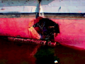
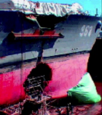
On 5 February 1999, while conducting exercises off Hampton Roads, VA,
the USS Arthur W. Radford was involved in a collision at sea with a
Saudi Arabian container vessel. The Saudi vessel's stem and bulbous bow
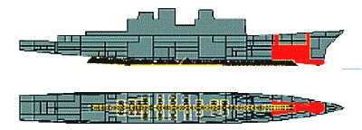
penetrated the starboard side of the Radford, centered near frame 69
(approximately at the location of the forward 5" gun mount). As a result
of the collision, the Radford experienced significant structural damage
and flooding from frames 58 through 94, with additional flooding within
sonar equipment spaces between frames 29 and 58. Post damage inspections
indicated that flooding was complete (free-flooded to the waterline).
Structural damage from the stem of the Saudi vessel consisted of
complete penetration of the side shell and main deck from the 1st
platform deck (24' above baseline) on the side shell to the ship's
centerline on the strength (01) deck, with damage extending mainly from
frames 52 through 84. Additional structural damage below the waterline
from the bulbous bow of the Saudi vessel consisted of complete
penetration of the side and bottom shell from the 2nd platform deck (15'
above baseline) to the center vertical keel at the baseline, with damage
extending mainly from frames 64 through 82. Outside these primary
penetration areas, there was significant buckling of decks and tripping
of stiffeners caused by the transverse force of the collision. Thus,
many of the structural members outside the primary penetration area
provided reduced effective strength to the hull girder.
Norfolk Naval Shipyard was tasked with stabilizing the vessel and
drydocking for initial assessment and planning for eventual
repair/replacement of the bow of the ship. Initial assessment of the
collision damage to the ship was provided utilizing POSSE. Additionally,
POSSE was utilized to provide assistance in the development of a weight
removal and deballasting plan for preparing the ship for drydocking on
25 February. POSSE was also utilized to provide an evaluation of the
drydock block bearing loads and ship's structural strength during and
following the drydocking process. Finally, POSSE was utilized to provide
an initial assessment of stability and structural strength of a
potential (proposed) refloating of the ship with the bow section removed
(forward of frame 94). The ship was drydocked at Norfolk Naval Shipyard
Drydock #3 on 25 February.
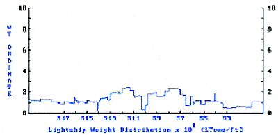
Initial Lightship Weight Distribution
The ship's initial (undamaged) condition was developed utilizing an
existing SUPSALV electronic POSSE model for the DD 963 class (with VLS).
This electronic POSSE model included full entry of hull and all
compartment offsets into the 3-dimensional electronic model, in addition
to representation of a number of ship structural sections for
longitudinal strength calculations. Lightship weights (weights, centers,
and longitudinal weight distribution) were based on class data and
modified to match DD 968. The initial (intact) load case was developed
based upon detailed weight logs provided by Norfolk Naval Shipyard,
matched to the ship's underway drafts.
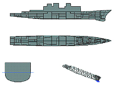
Hull Stations/Offsets and Compartmentation
Back to Top
Detailed Description of Structual Failure
- Collision Damage Assessment:
As a result of the collision, the Radford experienced significant
structural damage and flooding from frames 58 through 94, with
additional flooding within sonar equipment spaces between frames 29
and 58. Post-damage inspections indicated that flooding was complete
(free-flooded to the waterline).
POSSE was used to calculate trim, stability, and residual
strength of the Radford in the afloat damaged condition. Damaged
drafts were calculated to be 26.4' forward and 20.0' aft (trim of
6.39' by the bow). Actual drafts on 2/7/99 were 26'5" (26.42')
forward and 20'2" (20.15') aft. The ship maintained sufficient
transverse stability following damage (as indicated by the righting
arm curve and a GM of 3.16'). Subsequent evaluation of the righting
arm curve indicated that the stability met underway wind heel and
roll criteria of DDS079-1.
Damaged Hull Girder Strength Issues:
Structural damage from the stem of the Saudi vessel consisted of
complete penetration of the side shell and main deck from the 1st
platform deck (24' above baseline) on the side shell to the ship's
centerline on the strength (01) deck, with damage extending mainly
from frames 52 through 84. Additional structural damage from the
bulbous bow of the Saudi vessel consisted of complete penetration of
the side and bottom shell from the 2nd platform deck (15' above
baseline) to the center vertical keel at the baseline, with damage
extending mainly from frames 64 through 82. Outside these primary
penetration areas, there was significant buckling of decks and
tripping of stiffeners caused by the transverse force of the
collision. Thus, many of the structural members outside the primary
penetration area provided reduced effective strength to the hull
girder.
With the significant structural damage experienced by the Radford
during the collision, the ship's hull girder strength was seriously
impaired in way of the damaged section. POSSE was utilized to
provide evaluation of the residual hull girder strength for the
damaged condition. Based upon structural surveys, damage was applied
to structural elements in the damaged section for purposes of
calculation of section modulii and shear areas. For structural
elements deemed completely ineffective, the elements were removed
from section modulii and shear area calculations. For structural
elements deemed only partially effective (i.e. due to partial
buckling of plating and/or tripping of stiffeners), the elements'
effectiveness was reduced by applying a "corrosion " factor,
reducing the contribution of the elements to the section modulii and
shear area calculations. The damaged section (e.g. at frame 69) was
calculated to have lost up to 60%of its original section modulii (to
both keel and deck) and approximately 35% of its shear area about
its horizontal neutral axis (i.e. for vertical bending and shear).
POSSE calculated bending and shear stresses in way of the damaged
section. Maximum stresses were under 30 ksi compression at the keel
and 15 ksi tension at the strength (01) deck for bending, and under
5 ksi for shear for all potential damaged load cases envisioned. As
the hull structure is primarily HTS (High Tensile Strength) steel,
with a nominal yield strength of approximately 51 ksi, there was a
factor of safety of less than 1.8 to yield in the extreme elements
of the keel (compressive yielding). It should be noted that POSSE
utilizes prismatic beam theory in evaluation of hull girder
stresses. Thus, bending stresses are assumed to vary linearly across
the section, with maximums at the extreme elements (keel and deck).
Actual stresses do not vary linearly due to non-linear phenomenon of
shear flow and shear lag. However, for purposes of evaluating risk
of hull girder failure, experience has shown that this approach is
reasonably accurate, provided non-linearities are considered and
suitable factors of safety to hull girder failure are provided for.
In order to increase the factor of safety to yield in the damaged
structural section, additional stiffening members were fabricated
and welded to the hull. Three large (36" T) beams were welded to the
strength (01) deck, and one large (36" T) beam was welded to the
starboard side shell at the main deck level. These stiffening
members had the net effect of increasing the section moduli of the
damaged section by approximately 10-15% thus reducing maximum
bending stresses by 9-14% in the damaged section.
Most combatant ship structures are designed and built with
sufficient stiffness such that hull girder yield is the initial or
limiting mode of structural failure within the hull girder. However,
with the extensive damage experienced by the Radford, other modes of
hull girder failure may have become limiting at or near the damaged
section at frame 69 and needed to be considered. For example, with
unsupported stiffened panels near the keel (due to loss of adjacent
supporting structure), panels may first fail by buckling, or
stiffeners may first fail by tripping. This is important because
those elements near the keel were under high compressive stresses.
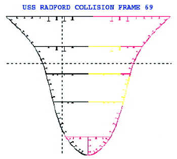
Damaged Structural Section at Frame 69
(black = fully effective, red = ineffective, yellow = partially
effective)
| SM COMPARISON TABLE |
| |
Intact |
Damaged |
% Loss |
| About Horizontal Neutral Axis |
|
|
| Area: |
1403.73 in2 |
77.23 |
44.60% |
| Ixx: |
3.47E+05 in2-ft2 |
1.50E+05 |
56.90% |
| SM-Upper Flg: |
20166.74 in2-ft |
9611.54 |
52.30% |
| Y Upper: |
17.22 ft |
15.57 |
|
| SM-Lower Flg: |
12262.32 in2-ft |
4993.71 |
59.30% |
| Y Lower: |
28.31 ft |
29.96 |
|
| Shear Area y: |
660.49 |
414.96 |
37.20% |
| About Vertical Neutral Axis |
|
|
| Iyy: |
1.65E+05 in2-ft2 |
49611.97 |
70.00% |
| SM-Left Flg: |
7455.3 in2-ft |
3279.09 |
56.00% |
| X Left: |
22.17 ft |
15.13 |
|
| SM-Right Flg: |
7443.79 in2-ft |
1696.04 |
77.20% |
| X Right: |
22.21 ft |
29.25 |
|
| Shear Area x: |
958.11 in2 |
605.04 |
36.90% |
| (computed at calculated extreme fibers) |
|
|
A new feature available with the Windows version of POSSE (still
in Beta testing) will be a capability to evaluate hull girder
ultimate strength utilizing the U.S. Navy's computer program
Ultimate Strength (ULSTR) as a peripheral application (i.e. run from
within POSSE). ULSTR performs a "limit state" analysis, and
evaluates the ultimate hull girder strength by calculating bending
moment necessary to yield, buckle or trip structural elements in
sequence. Elements also shed load following initial failure, and
thus adjacent elements must pick up the load shed by the failed
adjacent elements. This can lead to a sequenced collapse of a hull
girder, which may take place at or below bending moment levels which
first cause yield in the extreme elements. ULSTR was run within
POSSE for the evaluation of the ultimate bending moment capacity of
the damaged section at frame 69. Results of this analysis estimated
that the damaged section had lost up to 55% of its original moment
carrying capacity (with a factor of safety of less than 1.7 to hull
girder collapse). Additionally, the "limit state" analysis indicated
that initial failure mechanisms were associated with tripping of
stiffeners and buckling of "beam-column" elements (stiffened panel
elements), initiating at bending moment levels as low as 22,000
ft-Ltons. The maximum calculated vertical bending moment in any
damaged load case envisioned was approximately 15,000 ft-Ltons.
Thus, factor of safety to initial hull girder element compressive
failure was calculated to be less than 1.5.
- Weight Removal and Deballasting Plan for Drydocking:
In order to ballast and trim the Radford for entering Drydock #3
at Norfolk Naval Shipyard, a weight removal and deballasting plan
was developed which maintained acceptable stability and minimized
hull girder stress levels, while obtaining the desired trimming and
draft goals. Maximum allowable drafts for entering Drydock #3 were
established by the Shipyard at 22'6" forward and aft, with a goal of
0" trim, but a maximum trim of 1'0" by the stern. Trim by the bow
was not desirable. These drafts would provide for required 1' of
clearance over the drydock sill.
The weight removal/deballasting plan included:
- Removal of all of the nearly 300 Ltons of ordnance onboard.
Much of this ordnance was located in the forward magazines,
which were flooded, and was the goal of the early weight removal
for reasons of ordnance safety.
- Removal of anchors and chain. Removal of weight forward of
the damaged section (frame 69) was desirable in order to reduce
bending moment across the damaged section, in addition to
reducing trim by the bow and draft forward. The only removable
weights that met this goal were the anchors and chain.
- Removal of the forward gun mount. With the gun mount
dislodged as a result of the collision, it was believed to be
easily removable, providing a good trimming effect.
- Removal (lightering) of fuel oil (and compensating water)
from the forward compensated fuel bank. This was the only large
weight that could be removed, without resorting to significant
underwater work to repair the major damage to the flooded
compartments. Note: Removal of fuel oil from the forward fuel
bank required installation and satisfactory watertight integrity
testing of blanks on the 10" sluice lines between tanks
6-58-1/2-F and 6-94-1/2-F (port and starboard). If this could
not be accomplished successfully, removal of the fuel from this
forward fuel bank would not have been possible. As a backup, the
alternate plan included dewatering of the sonar dome using
ship's service compressed air and addition of drydock weights
(pier blocks) on the fantail to even out the trim. However, the
alternate would not include as much draft margin for entering
drydock.
With successful lightering, it was calculated that the vessel
would obtain drafts of 20.88 forward and 21.21' aft for entering
drydock. Stability would remain acceptable, even as lightering of
the fuel/water from the forward compensated fuel bank was
accomplished prior to ordnance removal. Minimum expected GM was
calculated to be 2.3 feet. The righting arm curve was evaluated to
meet underway wind heel and roll stability criteria of DDS079-1.
Additionally, maximum hull girder bending stresses in the damaged
section would be reduced to less than 25 ksi (compression at the
keel).
Following removal of ordnance, it was discovered that predicted
trimming effects were not obtained. It was subsequently concluded
that the ordnance weight and location information provided with the
loading condition information was apparently inaccurate. However,
despite this shortcoming, acceptable fore and aft drafts for
entering drydock were obtained, providing a 2' clearance over the
sill.
- Initial Assessment of Drydock Block Loading and Hull Girder
Bending Stresses in Drydock:
Per request of Norfolk Naval Shipyard Naval Architects, POSSE was
utilized to model the USS Radford in drydock. The "Multiple Point
Grounding" (MPG) feature in POSSE was used to model drydock blocks
(keel and side blocks), and evaluate effects of pumping down the
drydock on individual block loading, as well as on hull girder
stresses. Note that all damaged compartments drain into the drydock
as the dock is "pumped down", as they are open to "free-flood".
Additionally, the sonar dome would be dewatered during or shortly
following drydock dewatering.
Drydock blocking modeled using POSSE's "Multiple Point Grounding"
capability.
The drydock block buildup was modeled by 88 individual "grounding
points", at specified locations of the individual drydock blocks.
POSSE rigorously calculated reaction force on each of the individual
blocks required to satisfy force equilibrium. For the initial case
where the drydock is pumped down, but the sonar dome remains full,
individual block loads (in Ltons) were calculated to range from 194
ltons (on the aft keel block) to 21 ltons (on the forward keel
block). It should be noted that this approach assumes that the ship
is represented by a rigid body, with the given shape, weight and
center of gravity. Thus, the block loading distribution is
calculated based upon the ship's geometry (offsets), center of
gravity, and block distribution (locations). The hull was assumed
NOT to deflect due to the drydocking (i.e. "hull deflection" was set
to the default "no deflection of hull girder" in the "options" menu
in Salvage Response). One alternative under POSSE 2.2 is to allow
POSSE to calculate hull deflections based upon hull girder
structural strength and longitudinal bending moment, or "inertias".
However, this approach requires a complex numerical iteration for
the program to converge on a solution for both ground reaction at
the 88 grounding points, plus the hull girder deflections. This
multiple iteration scheme is numerically complex and does not
converge easily. In fact, in this configuration, convergence could
not be obtained with "hull deflection" set to "computed deflection
based on hull girder inertias", unless the number of grounding
points (i.e. drydock blocks) was reduced to a small number (less
than 10 in this case) and the "spring stiffness" was significantly
reduced to soften the force/compression curve on each block.
Predicted longitudinal bending and shear stresses are presented
below. Bending stress at the damage section was expected to reach 41
ksi at the keel (compression) and 23 ksi at the strength deck
(tension). The predicted bending moment at the damaged section was
calculated to be approximately 24,500 ft-Ltons, which would be in
excess of the ultimate bending moment capacity of the damaged
section, calculated based on ULSTR analysis. This was clearly
undesirable.
Given the undesirable stress levels and bending moment in drydock
with the sonar dome full, two possible steps could be taken to
reduce bending moments at this damaged section:
- Dewater the sonar dome prior to emptying the drydock or
dewatering the sonar dome during the drydock dewatering process,
but prior to the drydock becoming empty. This provides reduced
bending moments at the damaged section. Bending stress at the
damage section with the sonar dome dewatered were calculated to
be reduced to approximately 33 ksi at the keel (compression) and
19 ksi at the strength deck (tension).
- Add drydock blocking under the sonar dome foundation
(bellyband), thus reducing bending moments across the damaged
section. In order for this to achieve much effect on reducing
bending moments and stresses, the blocking under the sonar dome
would need to have sufficient height to ensure they are
sufficiently loaded to reduce bending moments across the damaged
section. For example, where blocks under the sonar dome are set
½" above the height contour of the sonar dome, bending stresses
across the damaged section could be reduced to 18 ksi at the
keel (compression) and 11 ksi at the strength deck (tension),
providing an acceptable factor of safety to yield.
For the drydocking, Norfolk Naval Shipyard included drydock
blocking under the bellyband of the sonar dome. This blocking was
set to the sonar dome offset heights, providing sufficient loading
of the blocking, since the bow/sonar dome had dropped approximately
1" due to relaxation of the structure since the collision.
- Initial Assessment of Refloating the Ship with the Bow
Section Removed:
Per request of Norfolk Naval Shipyard naval architects, POSSE was
utilized to model and evaluate the afloat condition of the USS
Radford with the bow section (forward of frame 94) removed. This was
done to determine viability of a plan to move the ship to another
drydock for installation of a replacement bow section. The modified
POSSE ship data files were developed by deleting hull stations and
compartments forward of frame 94,and adjusting weights (lightship
weight distribution and variable loads) by removing components
forward of frame 94. It was assumed (for the initial evaluation)
that all tankage and other variable loads remained the same as for
the initial drydocking condition. In this case, the stern section
should float with approximate drafts of 15.7' forward and 24.0' aft.
It should be noted that this forward draft is referenced to the new
"bow" of this stern section (i.e. frame 94), vice the original
forward perpendicular of the DD968. Stability of this stern section
in this condition would be excellent, with a predicted GM of 3.78'
and large righting arms throughout a large range of stability. While
this initial analysis was completed using the initial (drydocked)
loading condition, it is clear that some variation of loading would
be required for the ship to float at a more suitable (even) trim for
undocking.
Back to Top
End Result
As this POSSE model was CONFIDENTIAL, conduct of the POSSE evaluation
was inconvenient, although not problematic. Files required storage on a
single 3.5" floppy disc (1.44 MB), and occasionally salvage case files
not absolutely mandatory required deletion to make sufficient room on
the single floppy disc. It should be noted that POSSE models for larger
ships (e.g. aircraft carriers, amphibious vessels, etc.) could be
problematic since the models will not fit on a single 1.44 MB floppy
disc. It is recommended that users who anticipate use of larger
CONFINDENTIAL POSSE models consider acquisition of a Zip Drive (100-200
MB), vice requiring their hard drives be made CONFIDENTIAL in an
emergency.
Back to Top
|
